Below are the requirements for generator interconnection to the Owensboro Municipal Utilities system.
General System Information and DG Equipment Requirements
- All Customer requests for interconnection to the OMU system will be handled on a first come, first consideration basis. An application in idle for incomplete information will not be removed from the order of consideration unless requested information is not provided by the Customer within twenty (20) business days.
- OMU shall not serve as the Engineer for any proposed DG Systems nor recommend manufacturers, vendors, or technical experts to the Customer.OMU’s sole responsibility is to evaluate any proposed DG Systems for possible negative effects to the OMU System. Should a negative effect be discovered during one of the evaluation methods, OMU will notify the Customer of the issues that the proposed system will cause to the OMU System. OMU shall not be responsible to provide mitigation options or redesign of the proposed DG System to resolve any issues.
- All DG Systems shall be designed for interconnection at the Customer secondary-service voltage level. Customers proposing DG Systems shall have their facilities served off an isolated OMU transformer(s) from other OMU customers. Electrical service to other OMU customers may not be provided from transformer(s) serving DG Systems. Customer shall be responsible to pay for the installation of poles, transformers, and other equipment required to isolate the service of their facilities from other OMU customers.
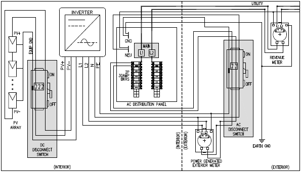
- All DG Systems shall have a manual, lockable, DG System disconnect switch located on the outside of the building as close as possible (10 feet or less) to the existing OMU meter. This disconnect switch shall be able to handle full-load breaking and completely isolate the DG System from the OMU System. Though the switch will typically be operated by the customer, OMU reserves the right to disconnect the DG System from the OMU System for emergencies or system abnormalities at any time without prior notification. OMU shall not be responsible to compensate the Customer for any power cost, lost revenue, etc. caused from the disconnection. If OMU determines system abnormalities are caused from the DG System, OMU will place a lock on the disconnect switch in the open position. OMU will notify the Customer in writing that the DG System has been locked out from paralleling with the OMU System and why. Customer shall be responsible to determine the cause for the disturbance and show OMU T&D Engineering proof that the issue has been resolved. Once OMU is satisfied with the resolution, OMU will remove the lock and allow interconnection operations to resume. The switch and enclosure should conform to NEMA, NESC, and NEC guidelines for such equipment.
- OMU’s “net” metering will be achieved with the use of two meters-a power used (revenue) meter and a power generated meter. All proposed DG Systems shall include an OMU approved meter base for the placement of an OMU meter to record the power generated. The power generated meter base shall be in a direct series path with the DG System disconnect switch and be in close proximity and on the same exterior wall to the existing OMU meter. A typical OMU approved small DG System is shown in this figure.

- For an interconnection of a proposed DG System to a radial distribution circuit, the aggregated generation, including that of the proposed DG System, shall not exceed 15% of the total distribution circuits annual peak load as measured by OMU at the substation circuit breaker. The total distribution circuit is defined as the mainline feeder and all branch lines from the substation breaker to the end of line or furthest tie point to other substations.
- The proposed DG System, in aggregation with other generation on the same distribution circuit, shall not contribute more than 10% to the distribution circuit’s maximum fault current at the point of interconnection to the primary voltage level.
- The proposed DG System, in aggregate with other generation on the same distribution circuit, shall not cause any OMU distribution protective devices and equipment or Customer owned equipment to exceed 85% of the short circuit interrupting capability. Additionally, a DG System shall not be proposed for an OMU circuit that already exceeds 85% of the short circuit interrupting capability.
- All DG Systems proposed to connect to the OMU System shall either be a three-phase or single-phase, phase-to-phase connection where the primary distribution line type is three-phase, three wire (Delta connection); or an effectively grounded three-phase or single-phase, line-to- neutral connection where the primary distribution line type is three-phase, four wire (Wye connection). These criteria’s shall be met to limit the potential for creating over-voltage issues on the OMU System due to a loss of ground during the operating time of any anti-islanding function.
- If the proposed DG System is proposed to interconnect on single-phase secondary, the proposed system shall not exceed 15 kW.
- If the proposed DG System is single-phase and it is to be connected to a delta or open-delta service via a center tap neutral, its addition shall not create an imbalance between the two sides of the 240 volt service of more than 20% of the nameplate rating of the transformer. Additionally, it shall not cause the load of any of the individual phases to exceed twice the load of any of the other transformers.
- The DG System, in aggregate with other generation interconnected to other circuits of a substation power transformer, shall not exceed six (6) MW per substation power transformer. This limit may be reduced at OMU’s discretion for areas with transient stability limitations or other operational issues.
- All steady-state and transient operating limits for voltage, flicker voltage, frequency, harmonic contents, etc. shall comply with the most recent versions of IEEE 519, IEEE 141, and ANSI C84. OMU requires the inverter to cease parallel operation to OMU’s System within six (6) cycles when any of the following criteria’s are met:
- OMU line voltage is less than or equal to 80% of nominal voltage (100 volts secondary)
- OMU line voltage is equal to or more than 110% of nominal voltage (137 volts secondary)
- Subsequent to the occurrence of events which causes the inverter to cease power production to the Customer or OMU System, OMU’s System voltage shall remain stable in voltage and frequency for a time not less than five (5) minutes prior to the DG System interconnecting to the OMU System again.
- OMU may request periodic testing of the DG System to ensure compliance with the designed and permitted interconnected equipment. This testing shall be done at the Customer’s expense and test reports shall be provided to OMU. The testing shall be done within thirty (30) business days of written notification from OMU. Failure to test and provide reports to OMU within this time frame will suspend the SGIA and OMU may disconnect the DG System from interconnection to the OMU system via the disconnect switch and place a lock on the switch until such test are performed.